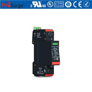
TUV certified Iimp 25kA Singe Phase VT Surge Arrester

- Prosurge
- China
- Within 25 days
- 10kpcs per month
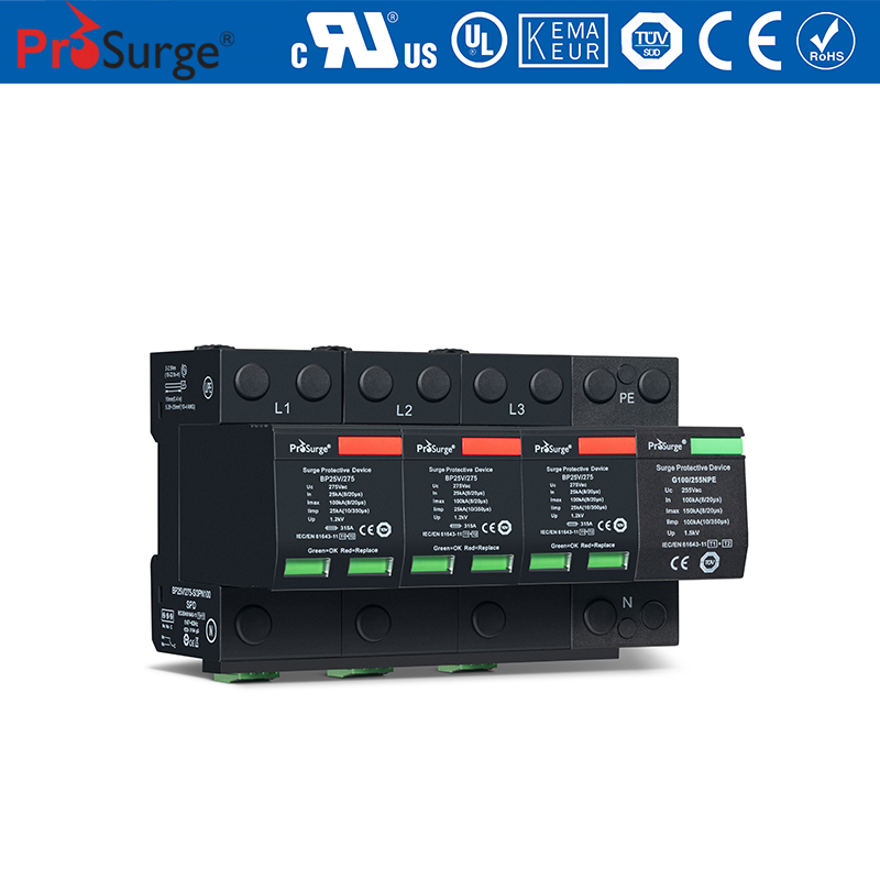
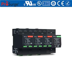
The BP25VT PN50 is class I & class II (or T1+T2 ) prewired two poles SPD designed for low-voltage power system lightning current & surge protection, especially for location of high risk exposure or LPZ 0-2 building entrances ( IEC 62305-4) to against the damage from direct or close lightning strikes.
With built in PROSURGE VT technology, BP25VT ensures remarkable lightning current discharge capacity up to 25kA 10/350μs and No leakage current & No follow current. It can be applied in most electrical installation and provide better reliability and safety protection, and particularly suitable for system with permanent insulation monitoring.
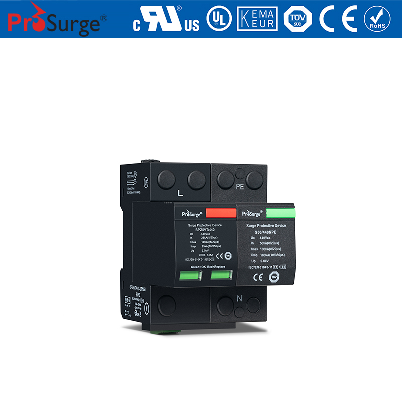
A notable feature of BP25VT is dual module redundancy design, two individual MOV protection modules in parallel in one pole SPD with two indication windows, so that the SPD could keep on working in spite of one protection module fault or one indication window turns to red. That will help to realize the uninterrupted surge protection, since user can replace the failure models according to the timing and the condition.
lTUV certified T1+ T2 SPD per IEC/EN 61643-11 standard
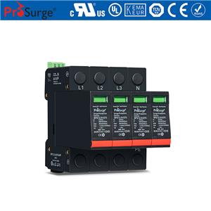
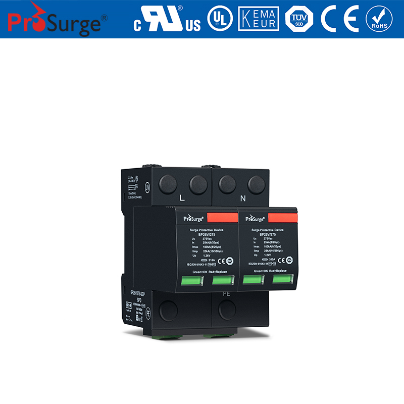
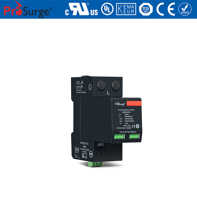
lPrewired two poles SPD (“1+1” circuit) for use in single phase
lUnique thermal disconnector design provides quick thermal response and secure disconnection
lDual module redundancy for one pole SPD and dual fault indication windows, with optional remote signal contact.
lLightning current capacity up to 25kA10/350μs (L-N), 50kA 10/350μs( (N-PE), Surge current capability up to 100kA 8/20μs
lLow voltage protection level due to VT tech.
lHigh short-circuit current rating up to 50kArms, suitable for application in most AC power system.
lLong service life because of no leakage current and follow current
lBetter reliability and robustness, Higher TOV (Temporary Over-Voltage) withstanding performance
lPluggable module for easy replacement without the need to remove system wiring.
lComply with UL1449 5th, IEEE C62.41,CSA C22.2 standards
BP25VT/150(-S)/PN50 | BP25VT/180(-S)/PN50 | BP25VT/275(-S)/PN50 | BP25VT/320(-S)/PN50 | BP25VT/350(-S)/PN50 | BP25VT/385(-S)/PN50 | BP25VT/440(-S)/PN50I | BP25VT/440(-S)/PN50 | ||
In accordance with | IEC/EN 61643-11:2011; UL1449 5th | ||||||||
Category IEC/EU/VDE | I+ II /1+2/ B+C | ||||||||
Protection mode | L-N ,N-PE | ||||||||
Max. continuous operating voltage(AC) Uc | L-N | 150V | 180V | 275V | 320V | 350V | 385V | 440V | 440V |
N-PE | 150V | 150V | 255V | 255V | 255V | 255V | 255V | 440V | |
Nominal discharge current (8/20) In | L-N | 25kA | |||||||
N-PE | 50kA | ||||||||
Max. discharge current (8/20) ] Imax | L-N | 100kA | |||||||
N-PE | 100kA | ||||||||
Lightning impulse current (10/350) Iimp | L-N | 25kA | 25kA | 25kA | 25kA | 25kA | 25kA | 25kA | 25kA |
N-PE | 50kA | 50kA | 50kA | 50kA | 50kA | 50kA | 50kA | 50kA | |
Voltage protection level Up | L-N | 0.7kV | 0.8kV | 1.0kV | 1.2kV | 1.4kV | 1.6kV | 1.8kV | 1.8kV |
N-PE | 1.5kV | 1.5kV | 1.5kV | 1.5kV | 1.5kV | 1.5kV | 1.5kV | 2.0kV | |
Response time tA | L-N≤25ns; N-PE ≤100ns | ||||||||
Temporary overvoltage TOV UT Withstand mode | L-N | 228V/120min | 242V/120min | 442V/120min | 442V/120min | 528V/120min | 528V/120min | 763V/120min | 763V/120min |
N-PE | 1200V/200ms | ||||||||
Follow current & interrupt rating Ifi | N-PE | 100A | |||||||
Leakage current Ipe | 0mA | ||||||||
Short-circuit current rating Isscr | 50kArms | ||||||||
Backup fuse(only required if not already provided in mains) | ≤315A gL/gG | ||||||||
Operating temperature range | -40ºC ~ +85ºC | ||||||||
Altitude | -500m ~ +4000m | ||||||||
Cross-section of connection wire (max) | Single-strand 35mm2; multi-strand 25mm2 | ||||||||
Mounting | 35mm DIN-rail in accordance with EN 50022/DIN46277-3 | ||||||||
Enclosure material | Thermoplastic; extinguishing degree UL94 V-0 | ||||||||
Degree of protection | IP20 | ||||||||
Installation width | 4 modules, DIN 43880 | ||||||||
Thermal disconnector | Internal Green – normal ; red - failure | ||||||||
Remote alarm contact | Optional | ||||||||
Approvals, Certifications | TUV, CE | ||||||||
Additional data for Remote Alarm Contacts | |||||||||
Remote alarm contact type | Isolated Form C | ||||||||
Switching capability Un/In | AC: 250V/0.5A DC: 250V/0.1A; 125V/0.2A; 75V/0.5A | ||||||||
| 1.5mm2(or # 16AWG) | ||||||||